Assembly From Scratch
This document describes how to assemble the racetrack from scratch. If you’re just assembling from storage, see assembly_from_storage.md.
Parts
See the bill of materials for a list of parts.
Electronics
Motor controller
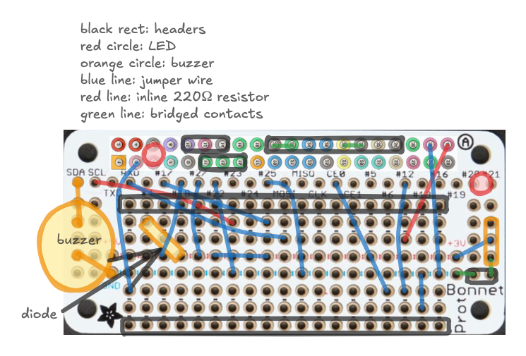
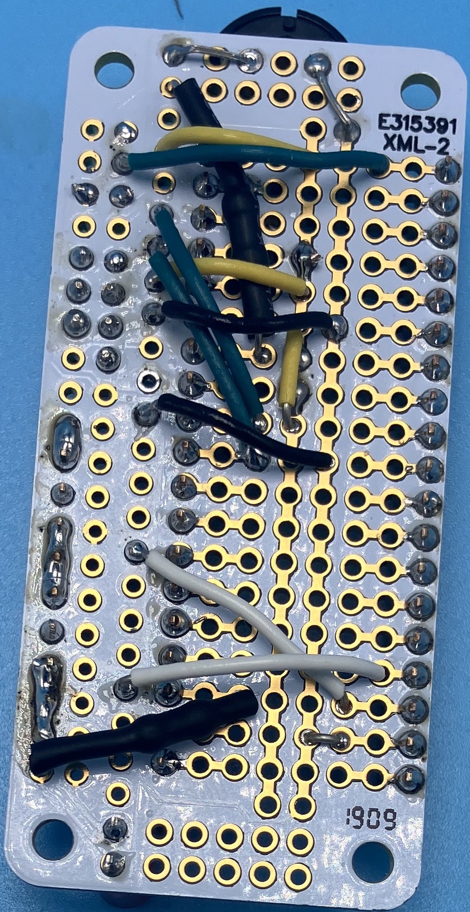
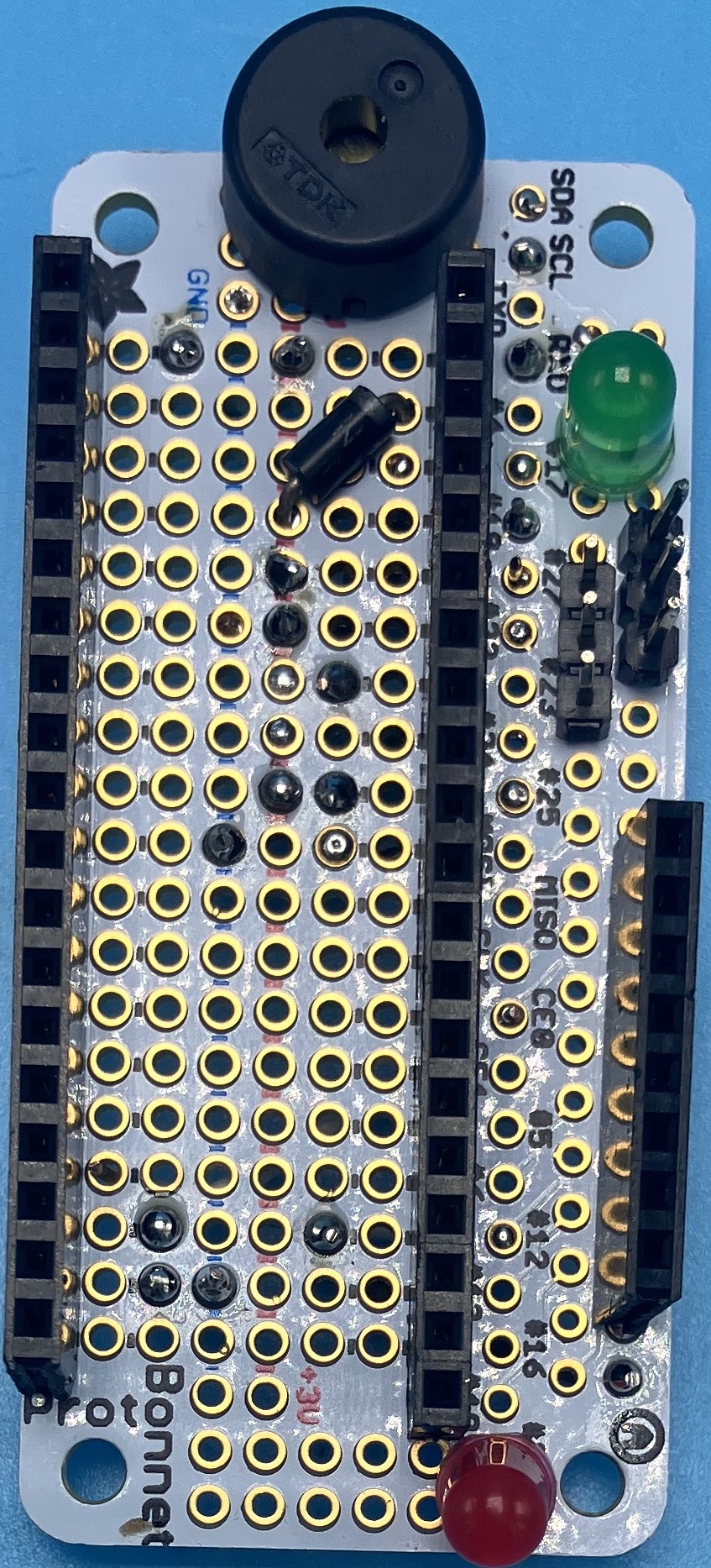
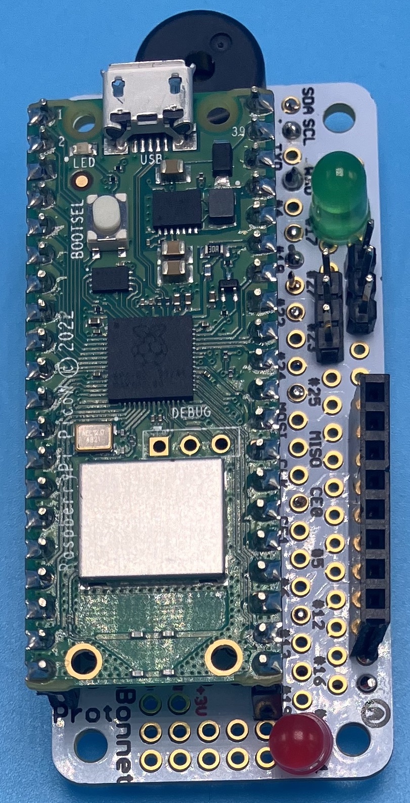
- Solder an Adafruit Perma-Proto Bonnet Mini according to the wiring diagram. Here are some pictures of what it should look like (albeit without the battery and switch).
Mainboard
- If you’re using a generic OLED instead of an Adafruit OLED, bridge the jumpers on the mainboard PCB accordingly.
- Solder headers and breakout boards to the mainboard PCB according to the schematic. I reccommend soldering female headers to the board for the Pico, RJ45 breakout and OLED but you can choose to solder them directly to the board if you wish.
- Run a bodge wire from GP20 on the unused pins header to an SDA pin. This corrects for the board incorrectly wiring GP22 to SDA.
LED board
- Solder 3 common-anode RGB LEDs to a strip of protoboard. Break out their anodes, red, and green pins to a header according to the silkscreened label on the mainboard PCB.
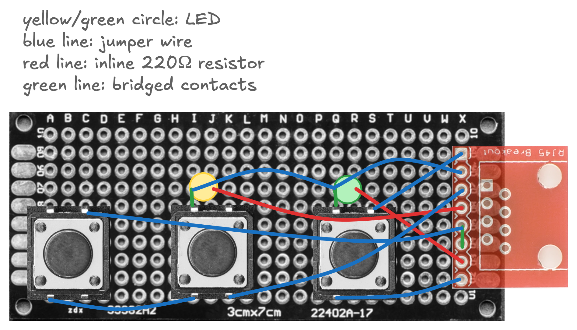
Race controller
- Solder a piece of protoboard according to the wiring diagram.
- Label the buttons with a labelmaker.
Structure
- Print out the 3D-printed parts.
- Using a soldering iron, insert the heat-set inserts. It may help to slightly counterbore the holes with a 1/8in bit, to help the inserts seat. It’s important that the inserts go in as straight as possible.
- Modify the beam-break sensors by carefully drilling out their bolt holes to 1/8 in. Then, for the emitters, terminate their wires with a female DuPont connector. For the receivers, extend their wires to ~320mm and terminate with female DuPont.
- Bolt the various electronics onto the 3D-printed frame. The mainboard, motor controller, and LED board are installed on standoffs.
- Neaten up the cables with zip ties.
- Bolt the pieces together and connect the electronics to the mainboard according to the silkscreened pinouts.
See the pictures for several pictures of the final assembly.
By this point you have all the subassemblies needed to follow the assembly from storage instructions.