Assignment
For this assignment, we had to build a robot arm. To narrow down the endless possibilities, every student in the class came up with a problem or two they wanted to solve with a robotic arm and pitched it to the rest of the class. People picked projects they thought looked interesting, and groups of two were formed. Our group, Lucia Whitmore @lwhitmo and River Lewis @rivques wanted to create a robotic arm to automate the process of programming music boxes. This is done by punching holes in a paper tape to indicate notes and timing. We opted to use a gantry, as we had very independent orthogonal axes (X is note, Y is time, Z is punching axis) and wanted rigidity and accuracy.
Parts
- Metro M4 Airlift Lite
- 2 NEMA-17 stepper motors
- 2 micro servo motors
- 2 DRV8833 H-bridges
- 1 TT motor
- 1 NPN transistor
- 1 diode
- 1 full-sized breadboard
- 1 3/32" drill bit
- roughly 250 mm of 2020 aluminum extrusion
- 4 rubber bands
- 4 V-rollers and related hardware
- OpenBuilds stepper mount plate
- OpenBuilds idler mount plate
- assorted hookup wire
- assorted fasteners
- 3D printed parts
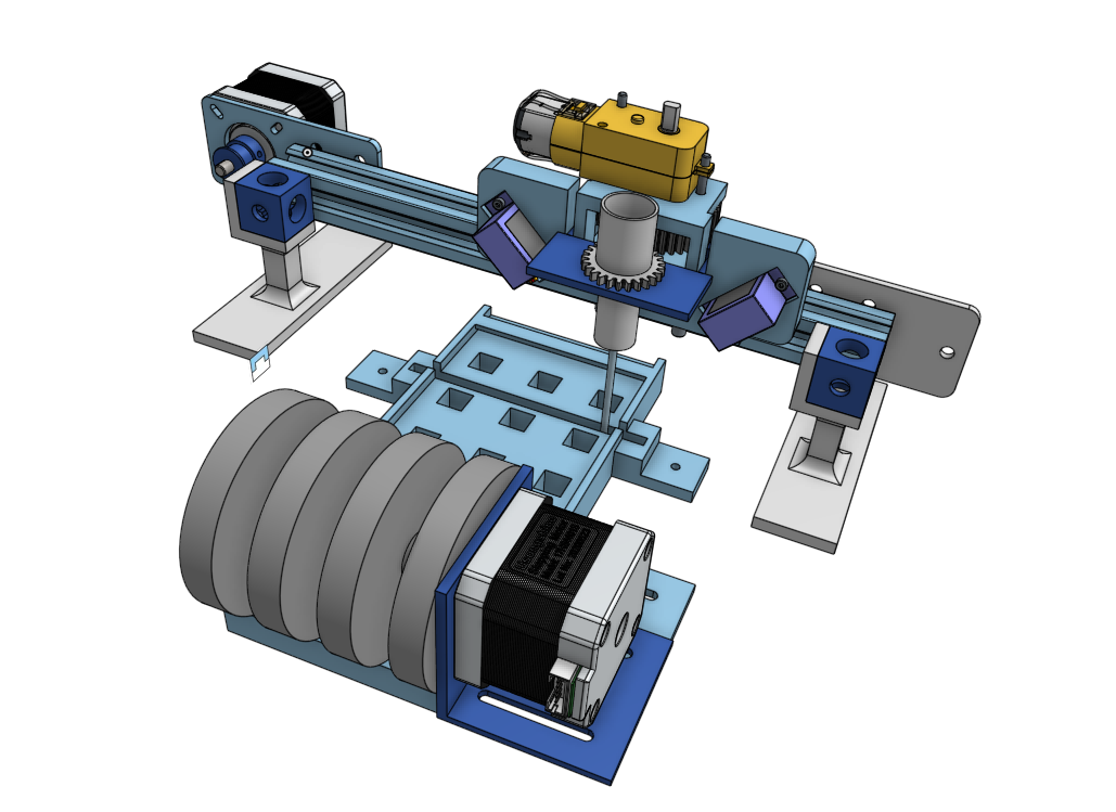
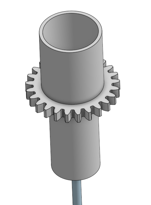
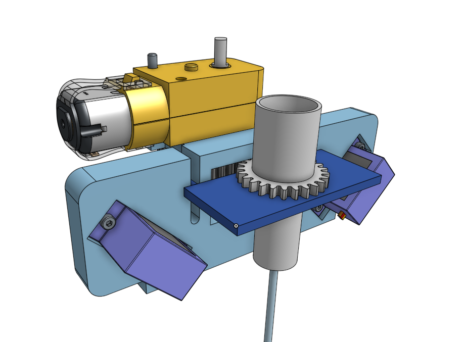
CAD
There should be captions under each image. If not, hover over the image to see the caption.
The CAD files are available on Onshape here.
Circuit
Our circuit is mostly just an interface between an Arduino-compatible and the various actuators: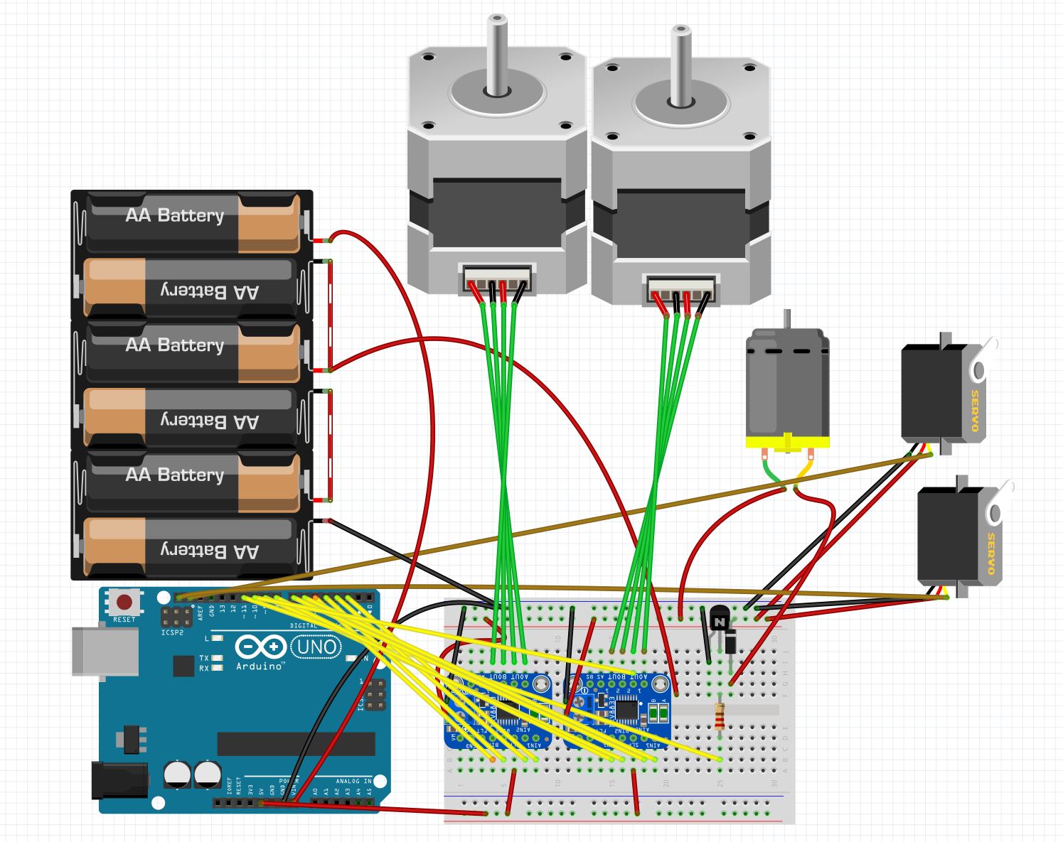
Code
The full code is available here. Interesting parts will be discussed below.
MIDI to Music Box
Fortunately for us, somebody else had already made a project like this and created a piece of software that could take in a MIDI file, automatically do a bunch of error checking, and spit out instructions for a robot like ours like PUNCH NOTE 12 or ADVANCE PAPER 12300. This saved an enormous amount of time learning the MIDI protocol.
Async
We knew from the start this program would be asynchronous, as we wanted to run both a user interface and the robot itself at the same time. With that in mind, we separated the code into a few main components: A UI function that would update the terminal as needed, a hole punching function that would iterate over instructions and execute them, a few helper functions to parse the instruction file, and a state machine to tie it all together.
Async input
One of the more interesting problems we ran into was that of taking user input asynchronously. We needed a coroutine that we could await that would return when the user had entered input but allow other tasks to happen while waiting on the input. We eventually ended up doing this by polling supervisor.runtime.serial_bytes_available, which is True when there is data waiting on the serial line, and calling await asyncio.sleep(0) while there was nothing to allow other tasks to run.
Memory issues (in Python! what fun!)
While figuring out how to make the TUI continuously update, we started running into hard-to-pin-down MemoryErrors. After generous logging (which somewhat exacerbated the issue, because logging records take up memory even if they aren’t printed) and digging through the asyncio’s code, we realized the issues stemmed from our use of asyncio.run(), like this:
async def run_ui(self):
    # ...
    await asyncio.sleep(.25)
    asyncio.run(self.run_ui())
    return
It turns out that this recursion (which felt really clever at the time of writing) was causing the issues. Every time we called asyncio.run(), an entry would be added to a stack inside of asyncio. However, because run() blocks until it returns, older recursions of run_ui() would never return (because they were waiting on their children, which were waiting on their children, etc.). This caused a buildup of entries on that stack, which would eventually fill up the (small) memory on the Metro and throw a MemoryError. The solution ended up being to use an outside loop to run the function instead of using recursion:
async def run_ui_forever(self):
        while True:
             await holePuncher.run_ui()
…which can be run with a single asyncio.create_task() in the main program, avoiding the recursion issue. In retrospect it seems fairly obvious that it’s a bad idea to recurse a purposefully infinite loop, but in the moment we saw an opportunity for recursion, thought “ooh! We can use a cool CS trick!” and didn’t think too much more about it (until we spent hours later staring at it, of course).
Stepper control
We made our own stepper controller for this project. We needed a controller that could asynchronously run to any given position in millimeters (internally handling the math to go between linear millimeters and rotational steps). The Adafruit stepper library only offered the capability to make a single step (or microstep) in a given direction, so we built a controller around this. We originally attempted to include microstepping, but we ran into trouble with it and it turned out we were accurate to something like .18 mm with whole steps, which is more than enough for this application.
Text user interface
We made a TUI that shows the progress through the current file, the currently executing instruction, and the motor positions without spamming the serial log. We do this by recording the length of the last printed line, then deleting it and writing the current state in its place. One quirk we ran into is that transmitting the backspace character \b doesn’t actually delete the previous character, it just moves the cursor back over it. Because of this, in order to send a line, we:
- Send as many backspace characters as there were characters in the last message.
- Send as many space characters as there were characters in the last message, to overwrite it.
- Re-send the backspaces to get back to the start of the line.
- Construct the new status string and record its length for the next iteration.
- Send the new status string, making sure to end with the empty string
''and not the default newline\n.
Fabrication
The carriage
Order of operations was critical to the assembly of this part. Pretty much every new part blocked access to another. The biggest challenge we ran into was the attaching of the V-rollers that would ride in the aluminum extrusion. This was done with a really clever system of eccentric nuts. Basically, these nuts have an off-center hole in them, so the placement of the nut relative to the rest of the part (and thus the spacing between the V-rollers) can be easily tuned.
The drill bit
To securely attach the drill bit to its chuck, we tried a few options. We initially tried simply gripping it from the side with a rubber band, but this was far too weak. We ended up with melting the bit into place: We would heat the bit up with a heat gun, then push it into the perfectly-sized hole in our part. This causes the plastic of the part to melt slightly around the bit, securing it in place when it solidifies.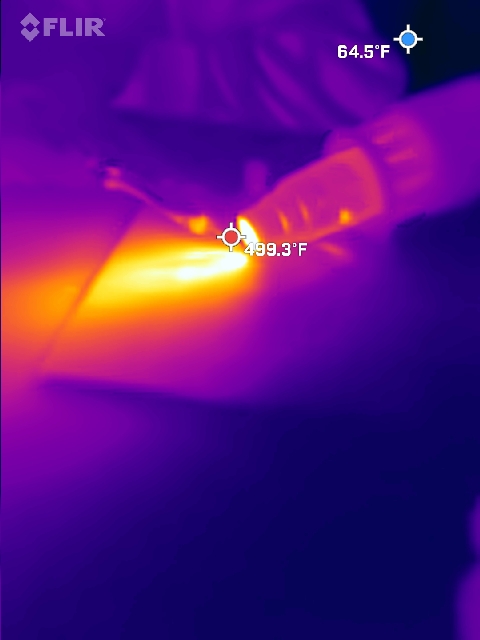
Process and results
Our full planning doc is here.
Plan A - Drill Bit
We originally planned to use a drill bit to drill a hole through the paper. However, the weight alone of the drill bit was not enough to punch through the paper. We tried adding some copper shot to the drill bit holder to make it heavier, but this wasn’t enough.
Plan B - Drill Bit But Better
Next we tried adding a plate on top of the drill bit holer to forcibly pull the bit down instead of just letting it sit under its own weight. We also corrected the spin direction of the drill. However, this just stalled the drill bit against the paper.
Plan C - Solenoid
We tried pivoting to a 12v solenoid to punch a hole. However, the solenoid (by nature) was very strong at holding itself in its extended position but not incredibly strong along its stroke to get there. Because we needed high force along the stroke, this didn’t work.
Plan D - Wait Let’s Go Back To The Drill Bit
With the failure of the solenoid, and about 36 hours until the project deadline, we tried going back to the drill bit. We took a brand new, factory-sharp bit and superglued it in the holder (because it wasn’t tight enough to friction-fit anymore and there wasn’t time to print a new one.) And, with a human helping to push down, it drilled a hole! However, when we let it try to go on its own, the wire links between the servos and the Z carriage became untwisted under the higher load. To fix this would have required a larger redesign than we had time for, so we decided to accept our (temporary) defeat and wrap up documentation before the due date. We were very close to completeness, but our final product at the deadline wasn’t able to accurately drill through the paper. That said, we built an accurate X carriage on V-rollers, a multitasking controller, a paper feeder, and a (weak) endmill.
Reflection and Lessons Learned
Proof of Concept
Our proof of concept, which was a prototype of the Z carriage and drill, was never actually tested. We barely finished it before its deadline, so after submitting it we went straight into full development as we were behind schedule. If we had tested the proof of concept, we would have caught the (many) problems with our hole-making methodology with more than enough time to fix them. Instead, we only realized it when we were doing full integration and had little time to fix the problem.
So Many Prints
We ended up printing an enormous number of prototypes, mostly for the carriage. About half of these were used to develop code with while waiting for more design work to get done and the other half were instantly scrapped after a design flaw became clear. Most of these flaws were based on forgetting that hardware can’t magically appear in its position (and that said hardware usually needs a way for a screwdriver to get at it). On the next project we design, we have learned the hard way to think about how a part is going to get where it needs to be before putting it somewhere.
Scheduling
We set a nice schedule for this project at the beginning, but weren’t able to stick to it. This was mostly because the designs for the proof of concept took far longer than anticipated, and ate up about 3 weeks of time. This may have been because we tried to dive into CAD and hope things worked themselves out instead of first planning out exactly what would be going on on paper.
Integration Hell
Integration Hell is where you are when you are fixing all the problems that happen when different subassemblies are put together. It’s an inevitability on any project and, while the problems are surmountable, they take time to fix. Because of the previously mentioned scheduling difficulties, we only had a few hours of time with the project fully assembled (instead of the month our schedule anticipated). As a result, we ran into a design flaw and were only able to make one (unsuccessful and rushed) attempt at fixing it. The root cause of this is probably both the overly optimistic schedule and only starting to put in extra time to try to stay vaguely on top of things very late in the project.
A Side Quest - River
In fabricating the rollers for this project, I realized I had a perfect opportunity to explore arc overhangs, which are a method of 3D printing over thin air when it would otherwise be impossible. Ultimately we didn’t end up using the result of this endeavor because I couldn’t get the tuning right for the very large rollers we needed, but it was a fun tangent to explore.
CAD Reflection - Lucia
One thing that was not achieved, but would have been beneficial, is the order of operation in which you create sketches and parts. Through the process of creating the toolhead, I based a sketch off of a part that had not been created yet, which caused some problems down the line when we needed to go back and revise the sketch. Another important thing to keep in mind when CAD designing is to measure twice and cut once. Doing this would have solved some of our issues when talking about the amount of printing material that was used just for the toolhead. The last thing that is of vital importance is making sure all of the hardware makes it into the assembly. In the long run it does not save any time to flake out on a few screws and nuts. This issue is going back to how many prints we had and that we could have saved time, money and redesigns if i had just added some simple nuts and bolts. Mates are similar in this scenario because if something is not in the correct position, you could be saved lot of hassle if it is just in the right place to begin with.