Assignment
For this assignment, we had to build a project that implemented PID control in some way. People in the engineering class made groups, and our group was Vinnie Jones @vjones2906 and River Lewis @rivques. We chose to make a car that would use a PID loop to keep a certain distance between it and whatever was in front of it. To spice it up, we decided to make the car tuneable wirelessly. This would allow for increased ease of tuning at the expense of ease of setup and simplicity.
Parts
- 2 Adafruit M4 Metro Express Airlifts
- 2 prototyping shields
- 1 .96" 128x64 OLED
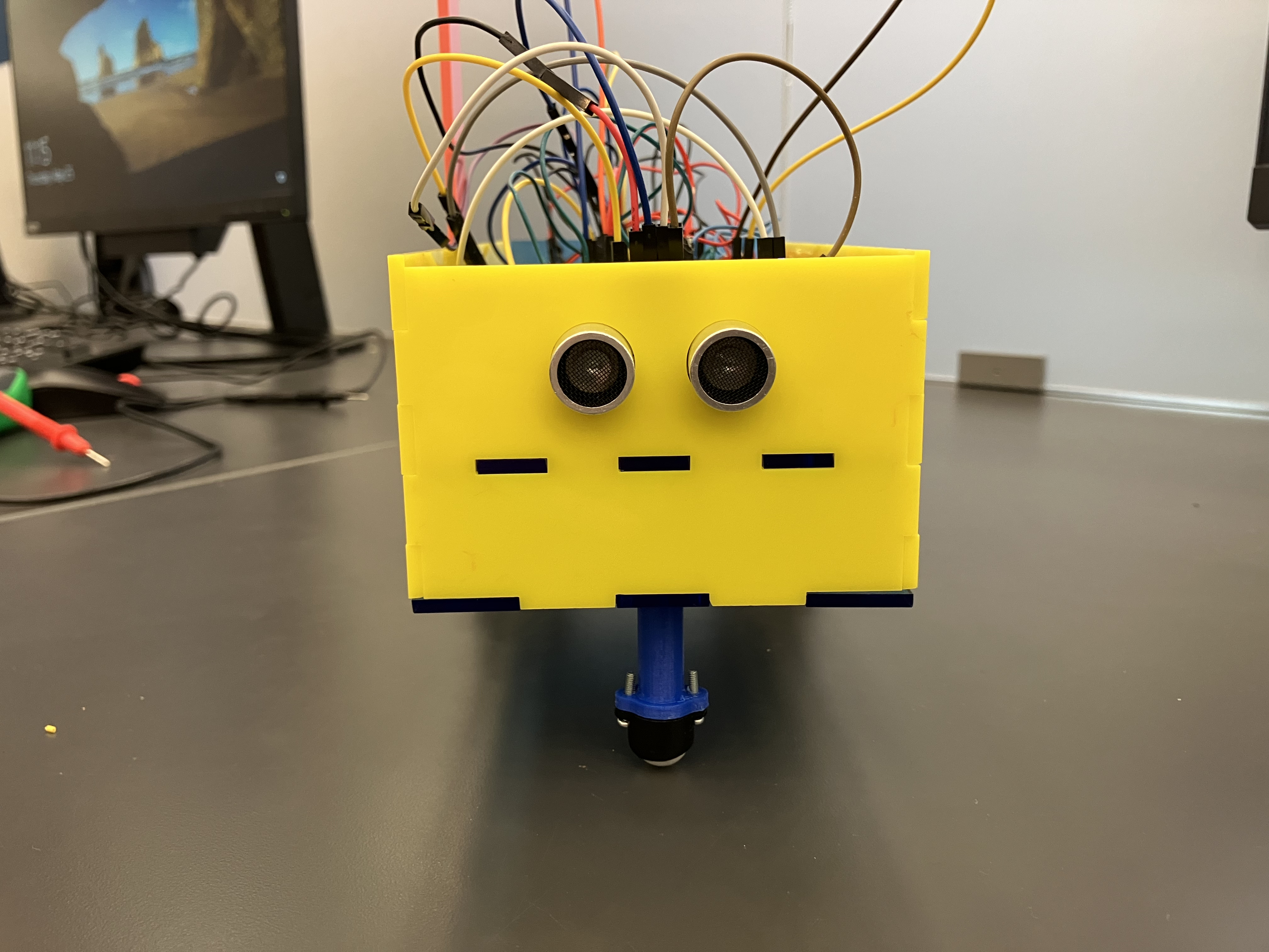
- 1 HC-SR04 ultrasonic distance sensor
- 1 SPDT panel-mount toggle switch
- 1 DRV8833 motor driver
- 2 TT motors
- 2 wheels
- 1 caster
- 1 LSM303DLHC magnetometer/accelerometer*
- 1 6xAA batter pack with an extra tap at 6V
- 6 AA batteries
- 3D printed and laser-cut parts as called for by CAD
- Assorted wires
- Assorted hardware
Tradeoffs Made
In the construction of the robot we made a few tradeoffs. This is a justification of some of the larger ones.
Wireless Tuning
| Gave Up | Got |
|---|---|
| Ease of setup | Ease of tuning |
| Stability | Unique feature |
This was a major feature of the car. It resulted in a tradeoff between ease of setup and stability of operation and ease of tuning and increase in construction difficulty. We made this tradeoff because we wanted we explore wireless functionality with the project and were okay with sacrificing some ease of use as long as we explained how to use it.
Two controller boards
| Gave Up | Got |
|---|---|
| Cost | Time |
| Space | Quarantine of poorly-behaved code |
This was a consequence of the WebSocket server we used. As discussed later, the sever pretty much refused to run in parallel with anything. Because these are all lab parts and will return to the parts bin after this project is complete, we felt is was better to use a spare Metro and find space for it on the build than spend time writing a custom firmware to run the WebSocket server on the ESP32 coprocessor onboard each Metro. In other words, there wasn’t an additional cost in practice, and it wasn’t difficult to find physical space for another board compared to either writing custom firmware or trying to convince the WebSocket server to be friends with the rest of the PID loop.
Media
Note: Depending on how you’re viewing this document, these pictures may have captions or you may need to hover over each image to read the caption.
CAD
CAD is available on Onshape here.
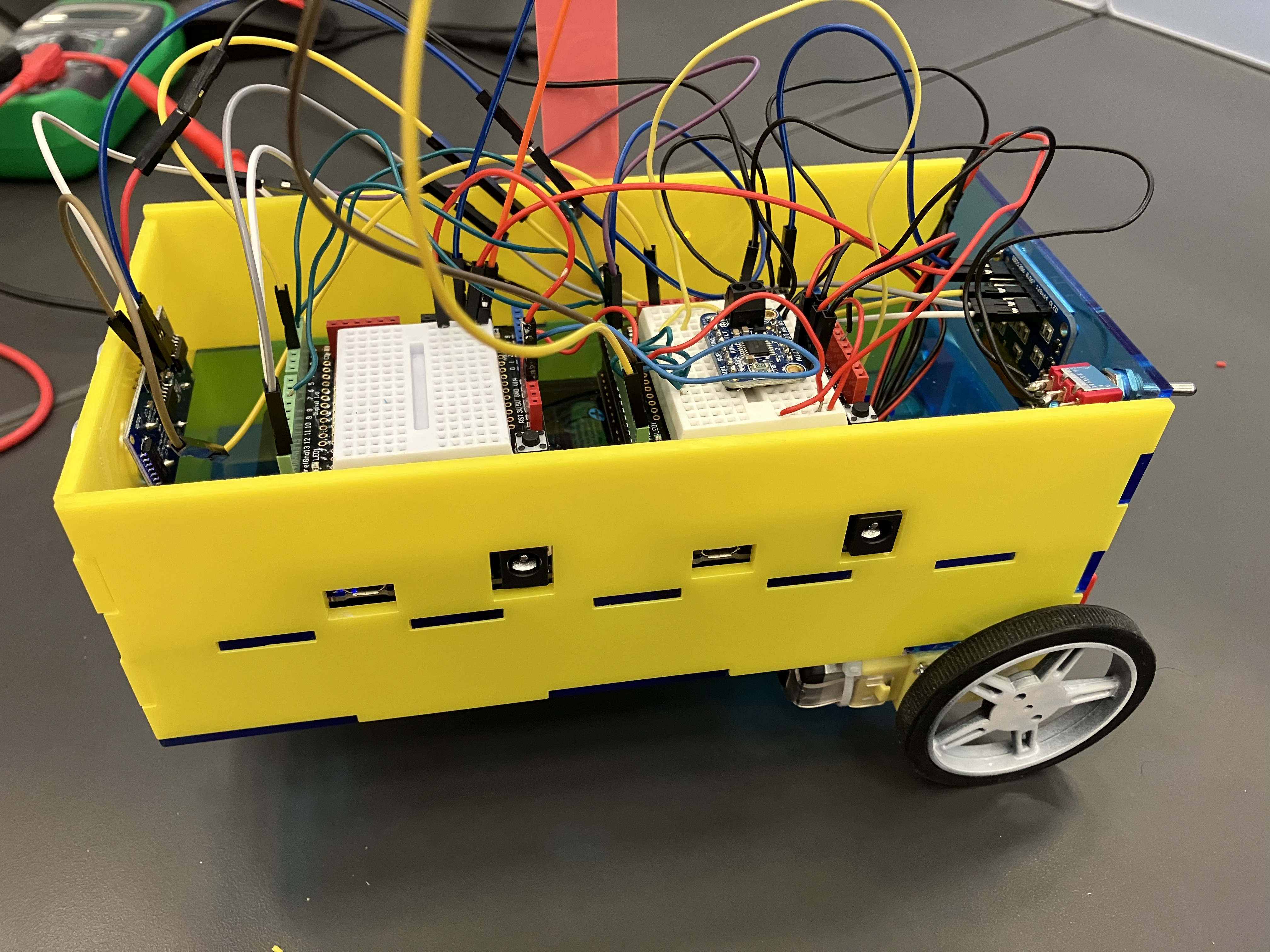
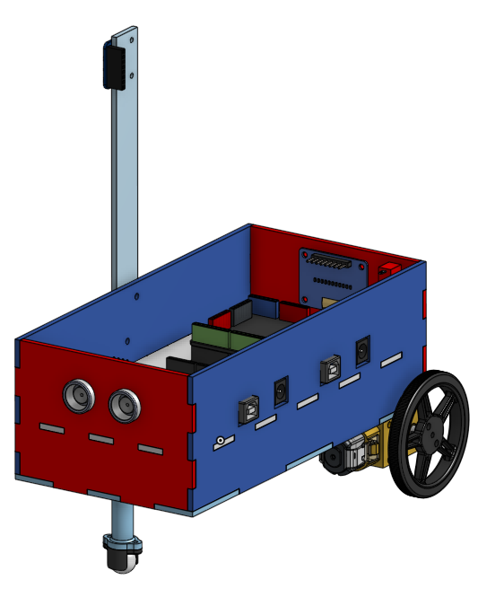
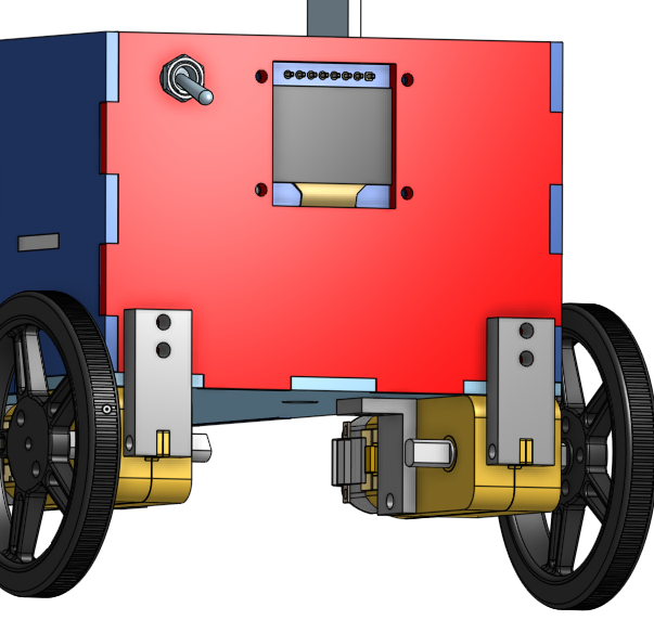
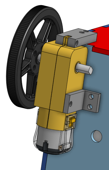
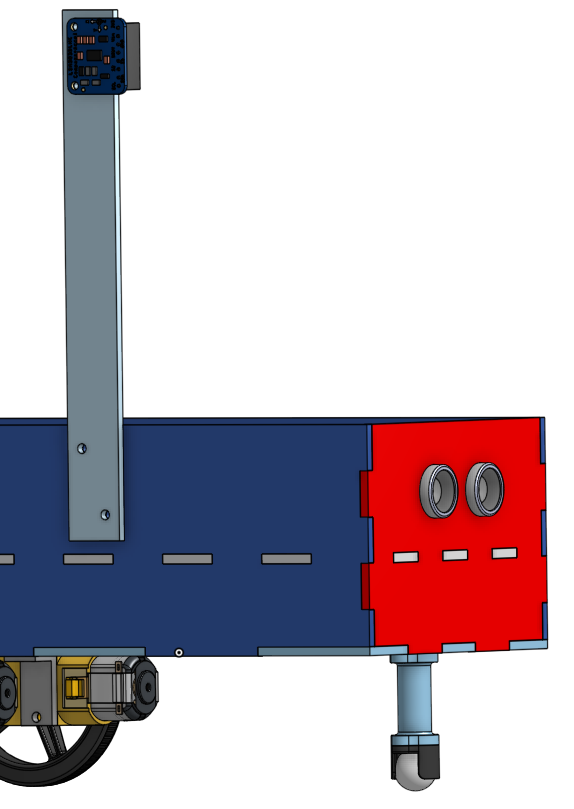
For the final design of this project we created a two-story box. On the lower level the batteries were stored, while the top held both Metro Expresses. The bottom of the design included a caster ball and its extension and 2 different types of braces to hold 2 TT motors. Holes were made to mount the ultrasonic sensor on the front, and there were holes for a power switch and OLED on the back of the car. On the side there was a “mast” which was a vertical piece of acrylic that was meant to keep the magnetometer away from the magnets of the motors providing for more of a precise reading.
Note: Depending on how you’re viewing this document, these pictures may have captions or you may need to hover over each image to read the caption.
Circuit
For reasons we will get into in the reflection section, there are two Metros communicating with each other over UART. One Metro is connected to an OLED, while the other is connected to the distance sensor, the motors, and the magnetometer. A power switch switches the ground. Normally it is bad practice to switch the ground, and ideally we would have had a double pole switch to switch both voltage lines instead, but it doesn’t cause any problems here.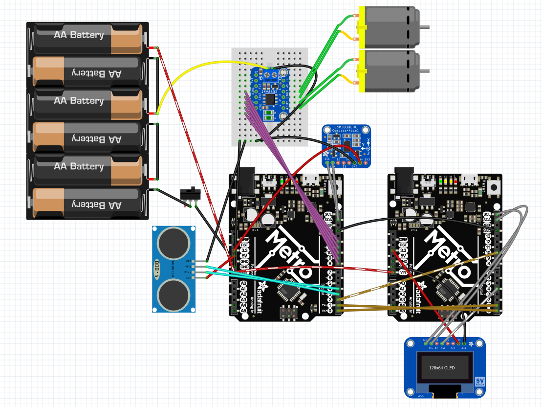
Code
The code is split into three parts: The car controller, which is in CircuitPython and runs the PID loops, the WebSocket coprocessor, which is in C++ and handles the communication between the car and the computer, and the web client, which is in HTML/CSS/JS and connects to the car and allows for wireless PID tuning.
Car Controller
Source code available here.
This runs on one of the Metros. It controls the motors, reads the distance sensor, and runs the PID loops. It sends its current PID state to the WS coprocessor over UART to be sent to the web client and occasionally receives new gains back. It utilizes Copper280z’s port to CircuitPython of m-lundberg’s simple-pid for Python based on Brett Beauregard’s PID library for Arduino.
WebSocket Coprocessor
Source code available here. Please note that this program expects to have a file called arduino_secrets.h in this folder, which defines const char* ssid = "YOUR_SSID_HERE" and const char* password = "YOUR_PASSWORD_HERE".
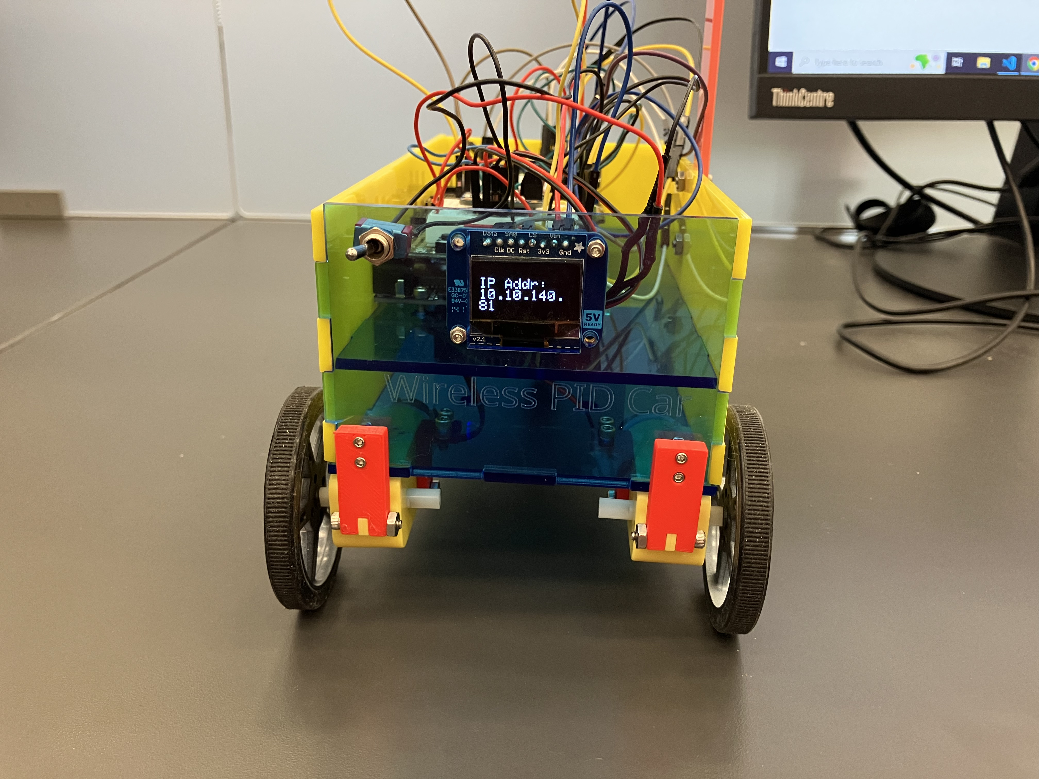
This runs on the other Metro. It basically converts a UART connection to a WebSocket connection. It also provides an OLED display that shows the IP address to connect to and other status updates.
WebSockets
I used the only WebSocket server library I could find that supported WiFiNINA, the protocol the Metro M4 uses to communicate with the ESP32 coprocessor. However, it had a few issues, which I will discuss below.
Soft Resets
Occasionally the WiFi would fail to configure properly, and resetting the board would fix the issue. However, we didn’t want to have to manually press the reset button, so we looked to see if there was a way to reset the board from code. After some digging, we found this StackOverflow answer, which kindly asks the underlying ARM architecture to reset by writing a specific value to a specific memory location. It’s a neat and convenient trick, as long as you are running an ARM processor like the SAMD51 the Metro uses.
Web Client
Hosted here, source code available here: HTML/CSS/JS.
This is a Web site which is capable of connecting to the car over WebSockets. It provides a live-updating graph of the PID state and allows for the tuning of PID gains.
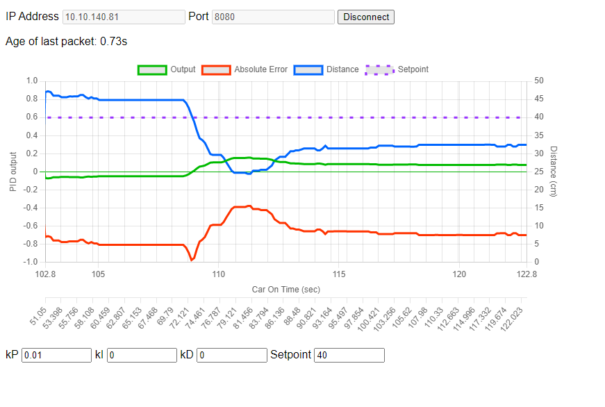
Live-Updating Chart
I knew I needed a live-updating chart, and Chart.js was the first library on the search results. It’s a very configurable tool that uses the HTML canvas to draw charts of many types. I was even able add a second Y-axis to the chart with a different scale for the PID output, which makes the whole chart fit together much better.
Mixed Content
Because this website is hosted on GitHub Pages, which is over HTTPS, and the websocket is not a secure websocket (because I didn’t want to deal with certificate authentication on the already unstable platform), mixed content needs to be explicitly allowed. Here’s how to do that in a few different browsers (paraphrased from this website): Firefox:
- Go to
about:configin your browser. - Search for
network.websocket.allowInsecureFromHTTPS. - Set the setting to
true. Note that this is a global setting, so you should change it back tofalseonce you’re done using the car. Chrome and Edge: - Click on the lock icon to the left of the URL.
- Click in “Site Settings” on Chrome or “Permissions for this site” on Edge.
- Scroll down to Insecure Content and set it to
Allow. This setting is specific to this site, so you don’t need to worry about changing it back once you’re done.
Fabrication
Our planning document is located here.
The fabrication of V1 went very smoothly… until we tried to install the OLED. All the bolts went in smoothly and all the parts fit as planned, but the space needed for the ends of the wires to connect to the OLED was overlooked and it was impossible the wire the OLED without bending the wires and compromising the connection. The fabrication of V2 came with a few problems though. The allowance of the laser joint was too little and the parts would not fit together. We messed with the allowance and re-cut a few of the parts. At that point they were so close to fitting so we filed the tabs down a tad and pushed them together with a lot of force. We’re not certain why this was needed, as the allowance had worked before, but it’s probably due to a high tolerance in the thickness of the acrylic we were cutting. All the attachments that needed to be screwed to the bottom were assembled first, then all the attachments to the second layer. The box was then assembled by putting the sides and second floor in simultaneously. Finally, all the side attachments were fabricated. Later on we decided that we needed the mast so we laser-cut it and installed it. However, the mast increased wiring complexity and was ultimately not needed, so it was eventually removed.
Use
To use the car, first turn on the power switch. The wheels may spin for a little before the WS coprocessor comes online, so hold the car off the ground until they stop. The OLED screen will display the connection status. Once it gives an IP go to the controller website and the connection information on the screen (after allowing mixed content). You will then be presented with a graph of the state of the PID loop. You can also change the gains and the setpoint of the car here. Here are some gains we found worked well:
Hard floor, cautious, no oscillation
P=0.01, I=0, D=0
Carpet, cautious, no oscillation
P=0.04, I=0, D=0
Carpet, fast, minor oscillation
P=0.13, I=0.01, D=0.003
Reflections
Code-CAD split
For this project we chose to have a very hard code-CAD split: Vince would do all of the CAD and River would do all of the code. This ended up working fairly well because both sections were finished within a couple days of each other, so one person didn’t have to wait on the other too much. It was also nice to be able to concentrate on just one thing and trust the other person to provide what was needed.
Code - River
Memory issues! (This time in C++! even more fun!)
Unlike last time, this memory issue was in the C++ code. Originally, the plan was to write everything in C++ on one board, because I couldn’t find a WebSocket server library for CircuitPython that supported using the ESP32 coprocessor. I got fairly far with this, but started running into an intermittent problem: Sometimes, after making a code change, the WebSocket connection would not be kept alive. This originally cropped up when using an LCD library, so I simply used an OLED instead, which worked. However, it turned out this was just a symptom of the problem. I eventually got to the point where I had a global variable declared, but if I ever accessed it, even inside of an if(false), the WebSocket connection would fail. Additionally, this behavior would only happen if said variable was larger than 16 bits. This made it incredibly clear that there was a memory issue somewhere. Even after removing all of the buffer operations I was doing (string parsing in embedded C++ is a nightmare), the issue remained. This isolated the issue to something in the WebSocket library. Lacking a debugger I could use to inspect memory, I instead elected to isolate the problem in its own box and never touch it again. I converted the program into what is essentially a serial-to-websocket adapter. It forwards any data it gets in over UART to a WebSocket client, and sends any data it receives over WebSockets out over UART. It also has an OLED display for showing its IP address and pin that indicates to the car controller whether there is a WebSocket client connected. I moved the rest of the on-car functionality to another Metro board. Because I didn’t need to do anything with WebSockets on this board, I was able to use CircuitPython and its much friendlier string processing. This solution was not the most cost effective, adding an entire extra processor to the BOM. However, this isn’t a big problem, as the lab has spares and these boards will go back into rotation soon anyways. If adding another board was a problem and I had more time, I probably would have written some custom firmware to run on the ESP32 coprocessor instead of Adafruit’s that took care of all the WebSockets and allowed the SAMD51 to run the rest of the car.
Host elsewhere and connect
Even though it is possible, I didn’t want to host the control website from the board. There’s a few reasons for this, but the ones I was most concerned about was that it would take too many resources to run and be too slow. Instead, I hosted the Web page elsewhere (first from the computer I was developing on, then on Github Pages once it was finished) and had it just communicate over WebSockets. I ran into a minor issue when moving to Github Pages: The website was now hosted over HTTPS, and it didn’t want to connect to the insecure WebSocket connection. I really didn’t want to deal with trying to convince the WebSocket library to run a secure connection and especially didn’t want to have to deal with certificates. Instead, the website kindly asks the user to allow mixed content or host the site locally on an insecure connection. This hints at a more fundamental problem with the “host elsewhere and connect to MCU” approach: Browsers make sure that HTTPS websites can’t talk to anything insecure, for the safety of the user, and most libraries don’t offer secure connections. If I end up making that custom firmware I might include secure WebSocket support or just rely on the trust of the user (which is usually me, anyways). Anyways, this approach can be very powerful if processor load is a concern and I intend to use it for future projects that need it.
Why WebSockets?
While I knew I wanted this project to be wireless, I wasn’t sure what protocol I would use. I investigated HTTP requests, BLE, and WebSockets. I didn’t use HTTP requests because I wanted the server to be able to update the client with low latency and not rely on the client polling (I later learned about server-sent events, which merit looking into for future projects). I experimented with BLE for a while, but while I was able to make the Metro show up in the NRF Connect app advertising serial capability, I wasn’t able to connect to it from a computer. I just don’t fully understand how BLE works, especially when it comes to pairing (I can’t tell if it’s even a thing for BLE devices). I ended up settling on WebSockets, because (after much searching) I found a library that was compatible with the Metro and could host a WebSocket server. If I couldn’t find such a library, my plan B was to have the Metro be a WebSocket client (which there exist plenty of libraries for) and connect to a server hosted on the controlling computer. However, this would have had some issues, namely that the controller would no longer be able to be a website (because they can’t host WebSockets) and that it would have been difficult to get connection information to the car easily. Fortunately, I was able to get the WebSocket server working, and the latency, while not perfect, is useable. I end up getting roughly 100-250ms of latency, spiking up to 1 second occasionally. I’m not sure exactly where in the stack this comes from, but my guess is that the car controller and web client are not major contributors.
CAD - Vinnie
V1
The first version of the car had no second layer which squished the battery pack and both Metro Expresses so tight that there was no room for the OLED wires to connect. The braces for the TT motors were not strong enough and posed a threat of breaking. It was also a pain if we had to change any of the wires on the bottom Metro Express because the other one was bolted directly on top.
V2
The second version had everything we needed, but it would have been nice to have added a few extra features. Two holes to bolt in the ultrasonic sensor could have kept it from falling out. I could have figured out the exact size of the different bolts before making the holes so some of them didn’t slide through the acrylic or 3D printed parts. There are also a couple of parts that have virtually no allowance and made our hearts skip a beat when we tried to install them for the first time (luckily they all fit). V2 had all the Metro ports on the port side of the car. This change was needed because there was not enough room to keep them facing the rear and still have clearance to access the wires. Once they were put on the second level and the ports on the left side it was much easier to access the wires and the OLED was able to be mounted on the back which looked nicer and was better for wiring purposes. The mast was mounted on the starboard side at the end because it was the only open space on the car. The switch was mounted on the back so it wouldn’t accidentally get switched off during use. The ultrasonic sensor, of course, had to be on the front so it could detect the distance. The batteries were put on the bottom level because we didn’t need to access them often and they would take up a lot of space anywhere else. The motors were put underneath the car so they were away from everything else and the wheels had clearance. We decided on 1 caster in the front because we didn’t need a second one and it was stable enough.
The magnetometer :(
After finishing the production of V2 and integration with code (ahead of schedule!) we here having some drift issues. We wanted to try to fix this in software by adding a magnetometer and a second PID loop to preserve our compass heading. However, preliminary tests showed that the motors were interfering with the magnetometer. To attempt to circumvent this we moved the magnetometer to the top of a mast, but it wasn’t enough and we were still getting garbage data. With deadlines approaching we chose to fix the root cause (the correct decision, but less cool than plan A) and improved the motor mounting, reducing the problem and giving us plenty of time to write documentation before the deadline.