FEA Beam Design
Assignment
This assignment is the first part of our introduction to finite element analysis (FEA), a technique for simulating how strong a design will be. We were challenged to make a 180mm cantilevered beam that could support the most weight among the class without flexing more than 35mm. The beam would be 3D printed in PLA and weigh no more than 13 grams. For the first part of the assignment, we couldn’t use FEA and had to design our best guess at a strong beam based off of our research and intuition. To start, my partner Jayden and I each designed our own beam; planning to use whoever’s worked better.
Document
The Onshape document is available here.
My Beam
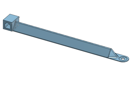
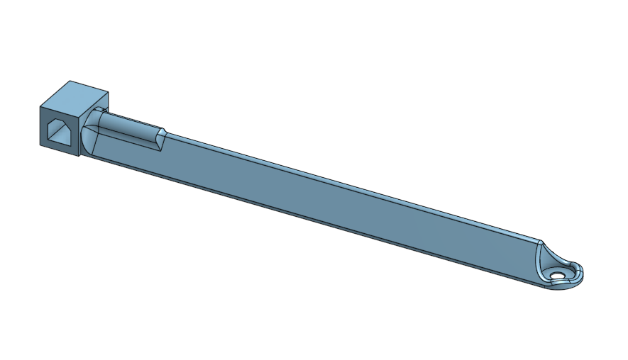
Images
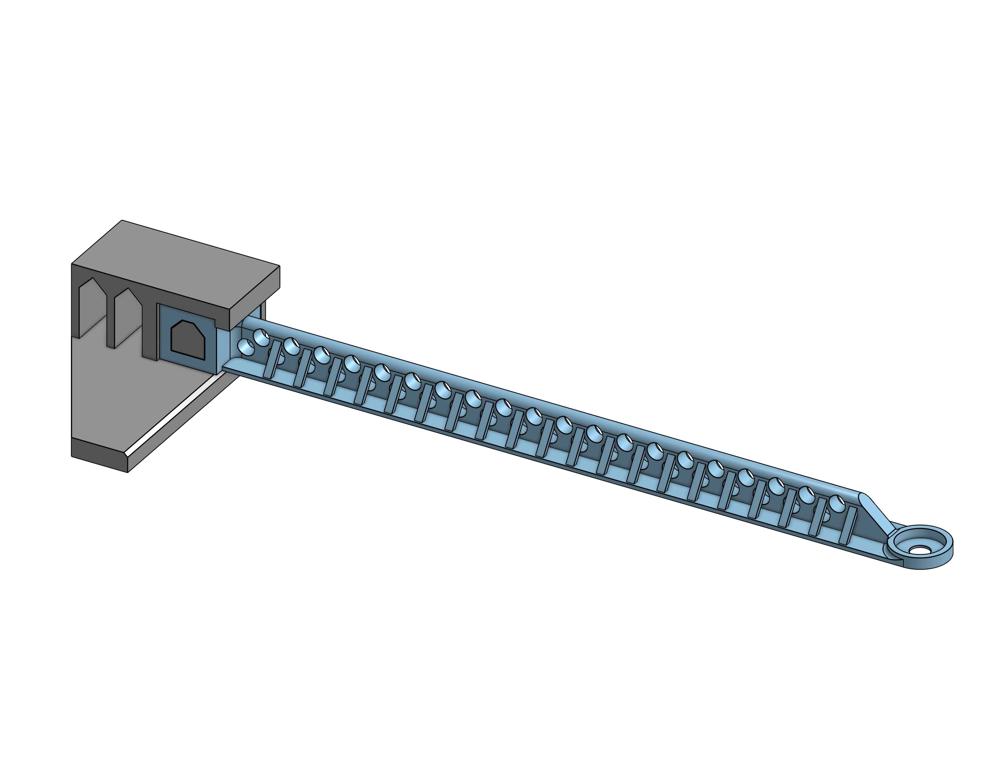
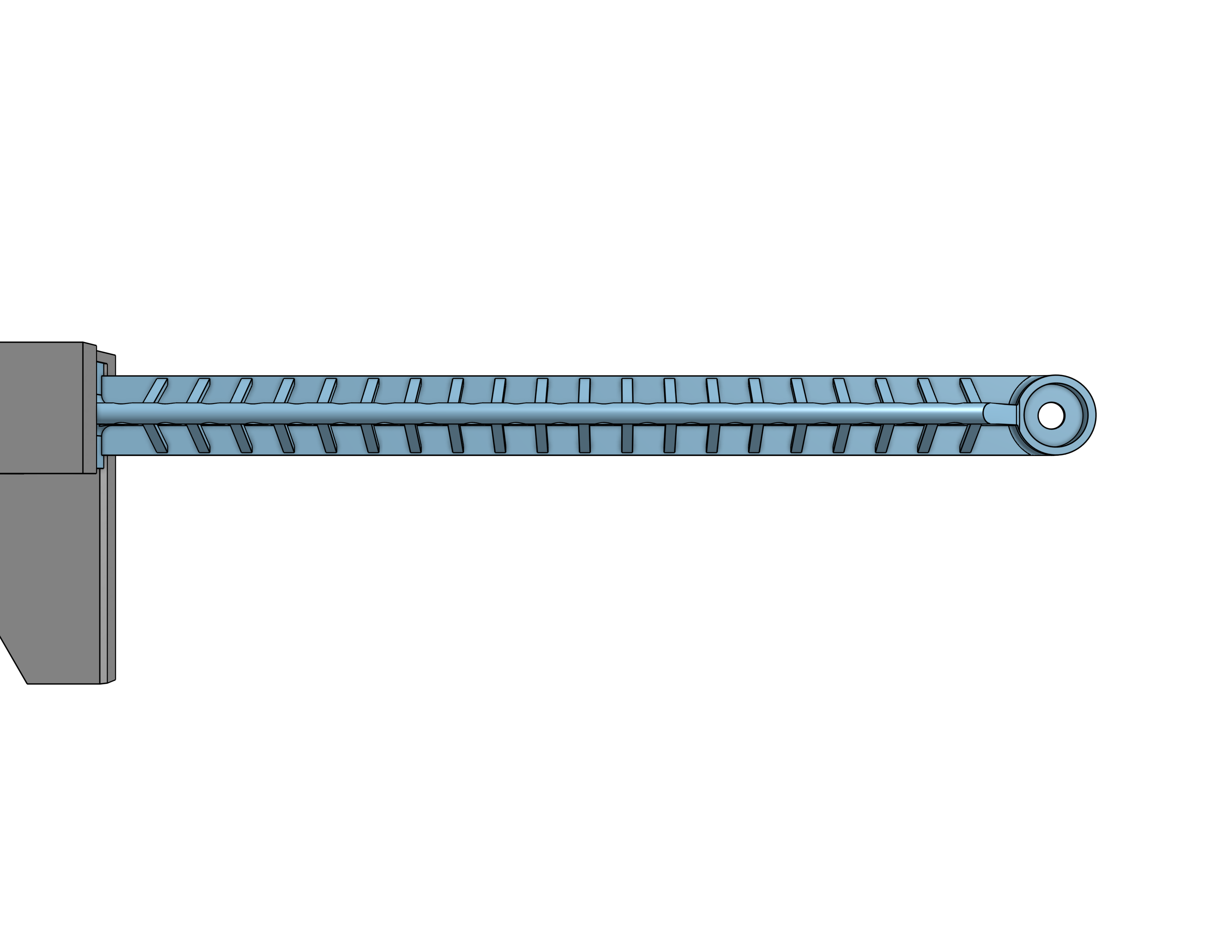
Design Reasoning
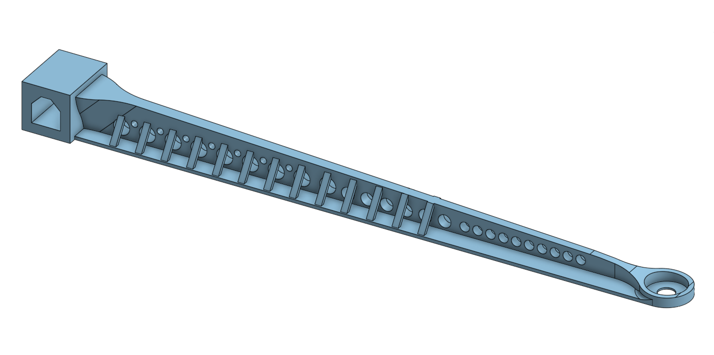
I went with an inverted T-beam as the base shape because that design did well last year. I added lots of lightening holes down the T to stay underweight. While the loading at the end of the beam is ostensibly straight down, I knew a few beams failed in torsion last year so I added some struts to try and stiffen it in that axis. The struts are very light so they don’t make much of an impact to the weight limit. One area where I know the beam could improve is in having more material near the mount point and less near the load to more efficiently handle the stress.
Jayden’s Beam
Images
Design Reasoning
Here’s Jayden’s reasoning for his design:
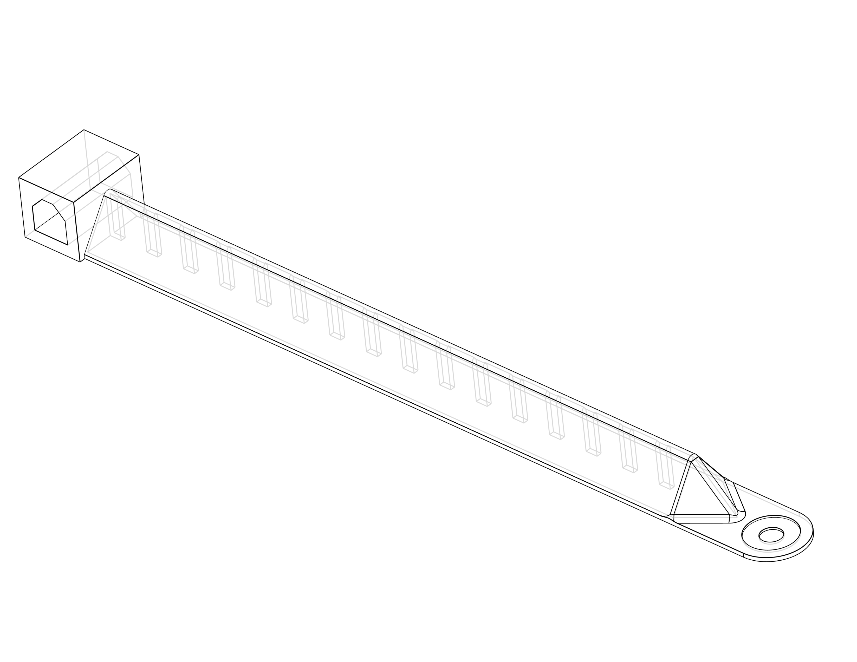
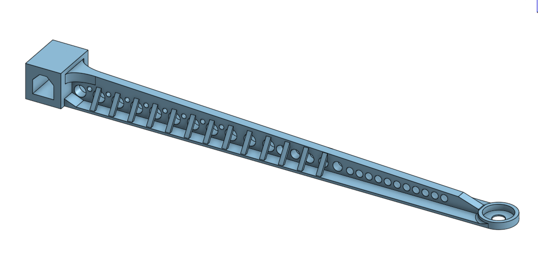
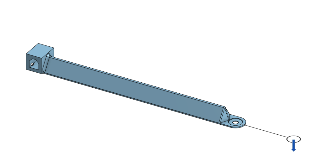
I went with a triangular design mostly on a whim, but it wasn’t completely silly. Triangles are strong, and I made it hollow to keep that strength while also making it as light as possible. I put tiny support beams inside of it because I figured that they might help, but I’m not completely sure what they’ll do. Essentially, I made a big Toblerone and hoped for the best. The main issue is that the part where the weights will hang from looks like it’ll just snap off.
FEA Beam FEA Analysis
Assignment
This assignment is an FEA analysis of the beam designed in part one. It will inform our future designs and tell us where we need add material and where we can afford to lighten.
My Beam
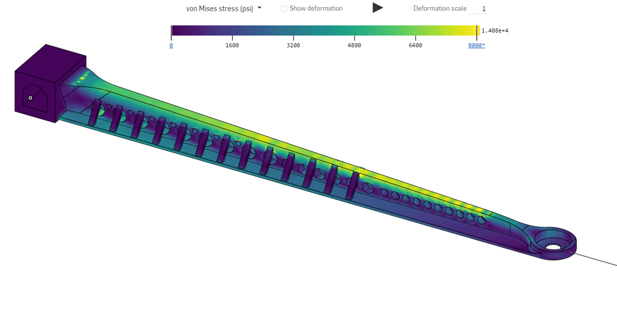
FEA Images
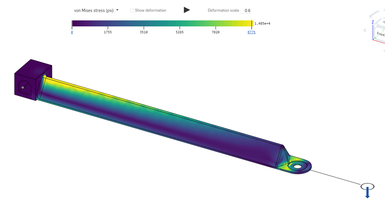
Analysis
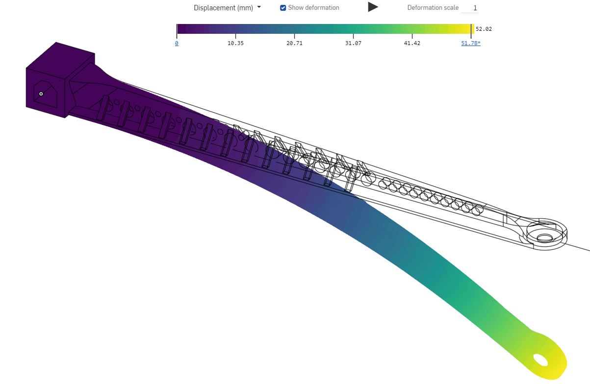
The stress is much stronger at the base of the beam, so I’ll move material there. I’ll get the mass budget to do this by removing material near the tip of the beam. The lightening holes are also very stressed, so I’ll remove those from areas that are already high-stress.
Jayden’s Beam
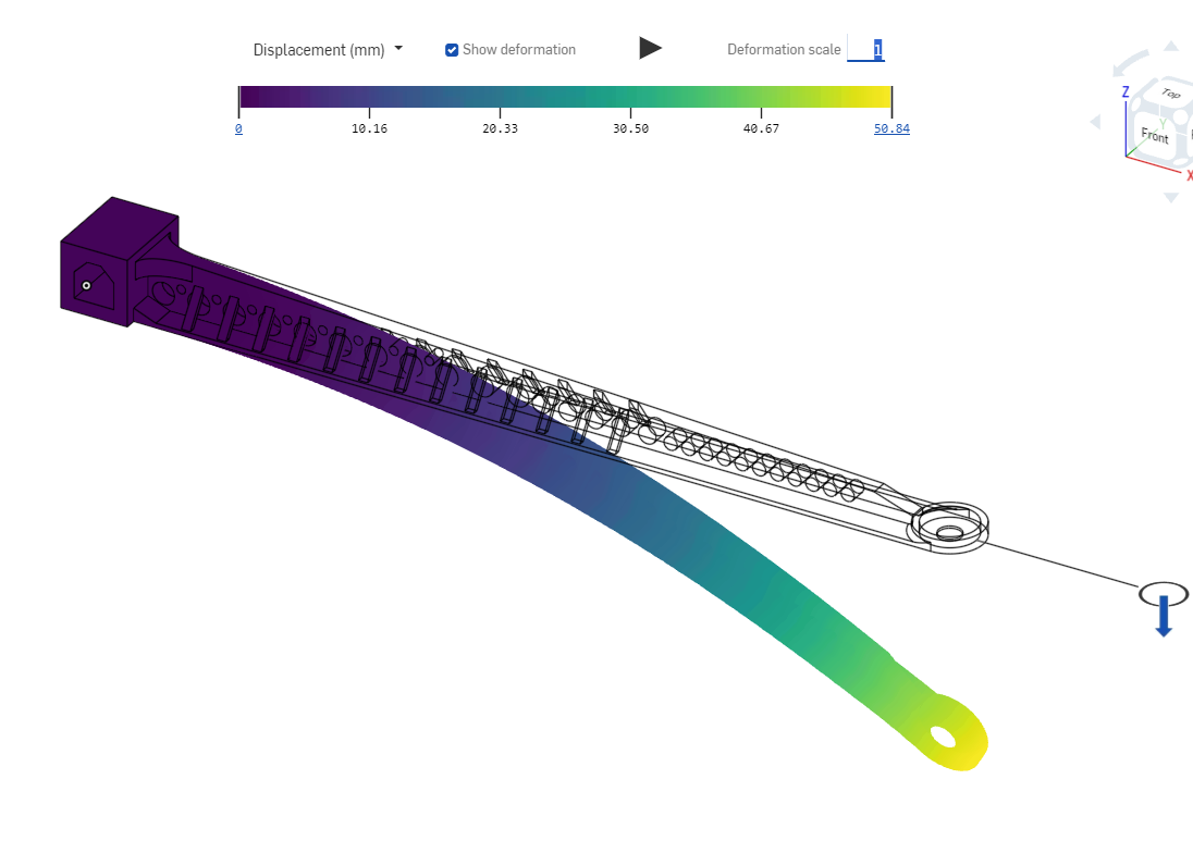
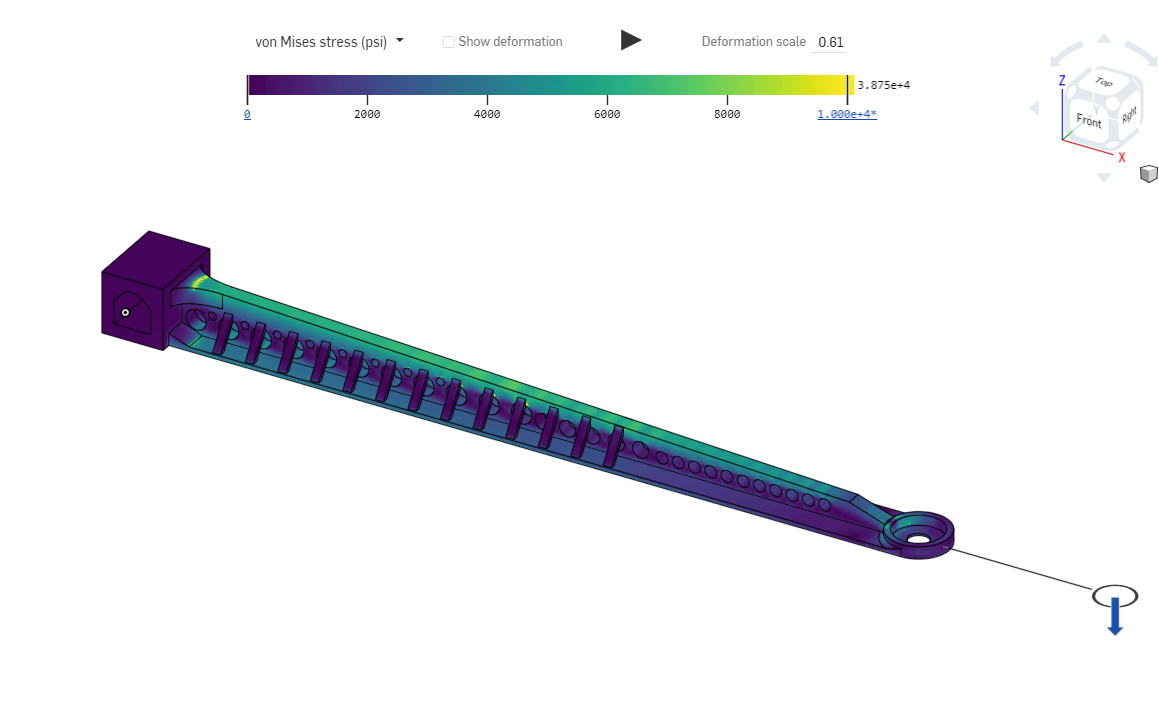
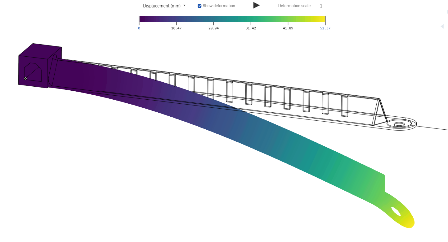
FEA Images
Analysis
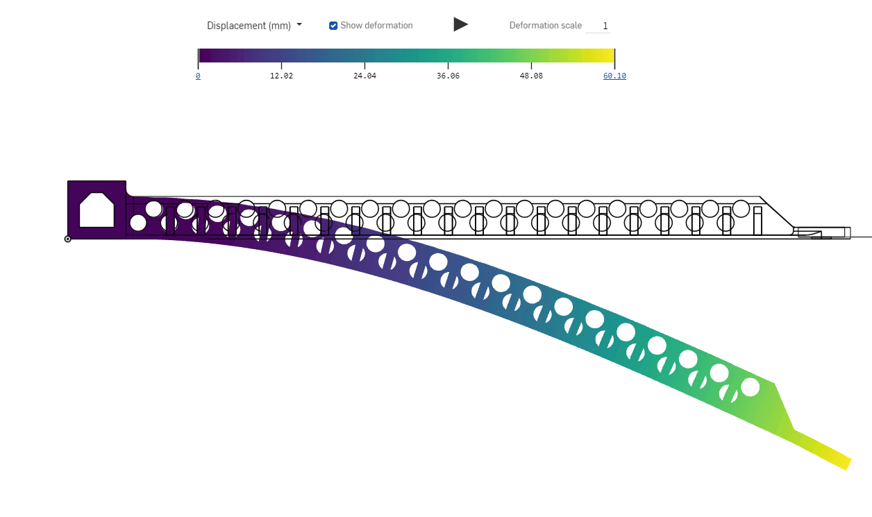
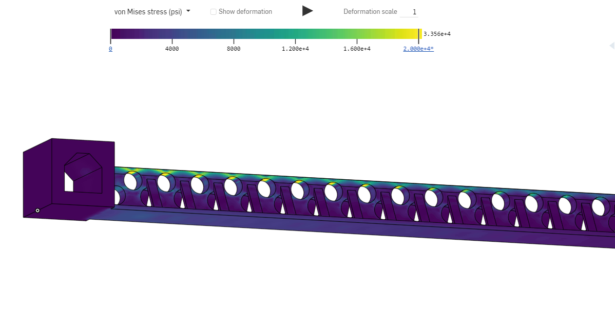
The stress model shows that there are two main weak spots, being the vertex where the actual beam connects to the attachment block of the beam, and the very end where the weight will hang from, as I predicted. I intend to use River’s startegy of adding little walls around that part of the beam to reinforce it. For the attachment block, I plan to add a fillet to that end of the beam to spread the stress out over a greater area. The displacement model shows exactly what you would expect; the end of the beam bends about 25cm too far, assuming it’s even able to bend that far in the first place. Reinforcing the triangle itself will limit its ability to bend.
FEA Beam Iterative Design
My Beam
New Version
FEA
Jayden’s Beam
New Version
FEA
FEA Beam Testing
Beam Selection
We were going to go with my beam because it had slightly better deflection. However, at the last minute we realized that my beam had illegal overhangs, so we pivoted to Jayden’s beam, which was nearly as good.
Beam Testing
FEA Beam Continued Iteration
I attempted to remove my overhangs while keeping the root of the beam strong and added a taper in the central T so it got thinner at the end of the beam. Jayden reinforced his beam where it broke.
My Beam V2
FEA
Jayden’s Beam V2
FEA Beam Final Testing
Beam selection
At the deadline, our final simulations revealed that while my beam had a lower max stress, Jayden’s had less displacement, and because our last beam failed by bending and not breaking we went with his. It was a well balanced beam, as had it not broken it would have failed by deflection at the same weight.
Media